
Cyber-physical energy systems
Cyber-physical energy systems are digitised, automated and information-enabled thermal-energy units, production facilities and enterprises in energy and industry. They include “smart” equipment, production lines and enterprises that automatically generate, convert, distribute and consume thermal, electrical or mechanical energy. Examples include power and heat generation, industrial production, smart electricity and thermal grids, smart buildings and the Industrial Internet of Things.
Physical industrial assets and embedded computing components are integrated through data networks, internet technologies and cloud computing. A cyber-physical energy system combines a controlled process—an asset, production line or enterprise—with an automated control system. Its operational technology spans industrial process and production control, enterprise-level integration, control theory and modelling, digital twins, machine learning, predictive maintenance, virtual and augmented reality, PLCs, HMIs, edge devices, intelligent sensors and actuators, SCADA, MES, business-process systems, industrial analytics, cloud and sensor networks, IIoT and cybersecurity.
Simulation, emulation and digital twins
Simulation models the structure and dynamics of a physical asset and the disturbances affecting it. Emulation models the asset’s structure and dynamics while using measured disturbances from the physical asset. An emulator is therefore a simulator connected to the asset through disturbances measured in real time.
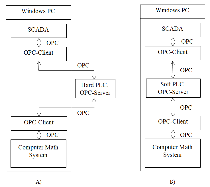
For an automated process complex (APC), disturbances may come from the control element, the load or a changing setpoint. Process characteristics can also drift over time, with age, season or daily operating conditions. APC simulation uses a software model of the controlled process and tests the controller and supervisory functions against it. The controller may be a physical “hard” PLC or a software PLC. Hardware-in-the-loop (HIL) simulation places a physical PLC in the feedback loop; software-in-the-loop (SIL) uses a software PLC. Figure 1 shows the HIL and SIL configurations.
A digital twin is a data-enabled digital representation of a physical asset used to support optimisation through the asset’s lifecycle. The description applies the Model–View–Controller pattern. A twin can be a DT Prototype (a model without live data), DT Instance (a model connected to live data) or DT Aggregate (interconnected models of multiple assets). Other classifications include DT Product, DT Process and DT System; a DT Collection groups twins, and a DT Environment is the physical setting with which they exchange data, such as a PLC.
Laboratory complex and software platform
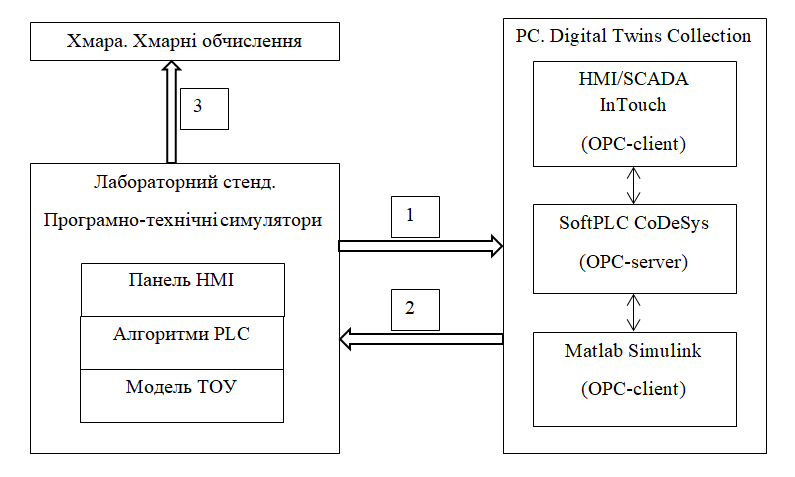
The complex is intended for software-and-hardware simulation and digital-twin work for energy and industrial APCs. It comprises a fixed HIL training stand based on a Unitronics OPLC Vision PLC; five mobile industrial-APC simulator stands based on Unitronics OPLC UniStream; a computer repository that stores and runs a collection of digital twins; a Simio simulator for production-logistics APCs; and an MQTT broker on the digital-twin repository.
On the physical training stands, the controlled-process model and supervisory functions run on the PLC and its HMI panel. The PLC serves as an edge device. The digital-twin platform uses Matlab Simulink for process models, CoDeSys software PLCs for controller functions and InTouch Edge HMI for supervisory functions. Software components exchange data through OPC/OPC-UA. Physical Vision PLCs exchange data with repository twins through PCOM/OPC; UniStream PLCs use Modbus TCP. Simio runs independently and exchanges recipes with InTouch Edge HMI through a text recipe file. Figure 2 shows the complex architecture and data flows.
Training and research applications
The stands support laboratory work in process automation, PLC programming, supervisory-system programming, APC simulation and industrial production automation. Students and researchers can develop and test controller and supervisory functions for energy and industrial processes without relying on access to the physical process itself. Related work includes the main Automated Process Complex Simulation Laboratory.
The training systems can be treated as representative APCs connected to their digital twins. Data exchanged with a twin include current operating values, setpoints, internal control disturbances and external load disturbances; the description also considers adding parameter drift. The described simulation compares a training system with its twin. The page describes machine learning and predictive maintenance as prospective extensions: a twin could return optimised controller settings or maintenance recommendations to the training system and its operators.
For production-logistics simulation, Simio models continuous, batch and discrete processes and generates schedules. Recipes are created in InTouch Edge HMI and implemented in CoDeSys and Unitronics PLCs.
For the proposed cloud applications, training systems send aggregated operating data and alarms through MQTT and SQL. Machine-learning functions could return optimised tuning values for process controllers; predictive-maintenance functions could provide recommendations for servicing and repairing the process equipment and automation system. The laboratory description places the MQTT broker and SQL database on the digital-twin repository.