6 Politekhnichna Street
Building 5, floor 8, room 801

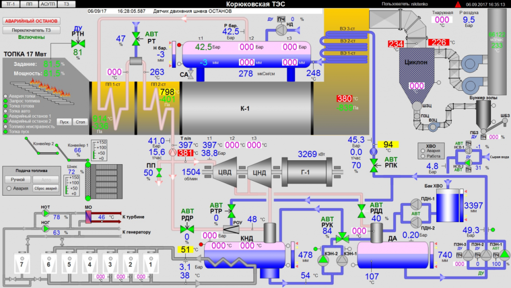
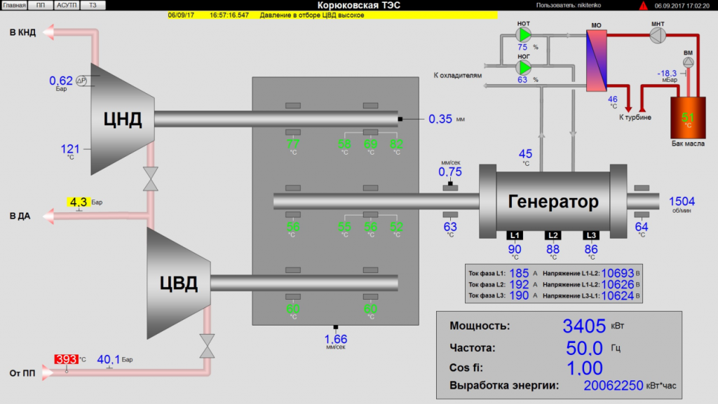
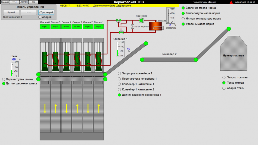
The Koriukivka thermal power plant in Chernihiv Oblast used wood residues as fuel. At the time covered by the project, the station belonged to Clear Energy. Fuelwood came from nearby forest enterprises and private suppliers and included logging residues and trees removed in sanitary felling. The wood was chipped, conveyed to a moving floor and fed into the furnace. Flue gas heated a waste-heat boiler, producing steam at about 40 bar and 400 °C for a turbogenerator. A multicyclone cleaned the flue gas; local farmers collected ash retained by the filters for use as fertiliser. Daily electricity output was reported at about 70,000 kWh.
The control system was designed for real-time automatic regulation, remote operation, process protection and interlocks. It collected, processed, displayed, logged and archived plant data; provided warning and emergency alarms; recorded operator actions; controlled valves and auxiliary machinery; and ran automatic logic sequences.
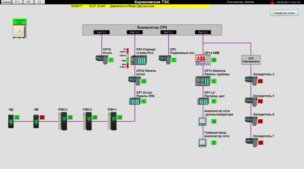
The lower control level used Siemens equipment: a CPU 317-2DP/PN controller, ET 200M and ET 200S distributed I/O stations, and a Profibus DP fieldbus joined through a four-channel ComBricks coupler. The plant-level installation comprised distribution, moving-floor, main-control, process-control and turbine cabinets; variable-frequency drives for feed and phosphate pumps; and control panels for cooling towers. Two operator workstations and an automation-engineering workstation connected to the central controller over Industrial Ethernet.
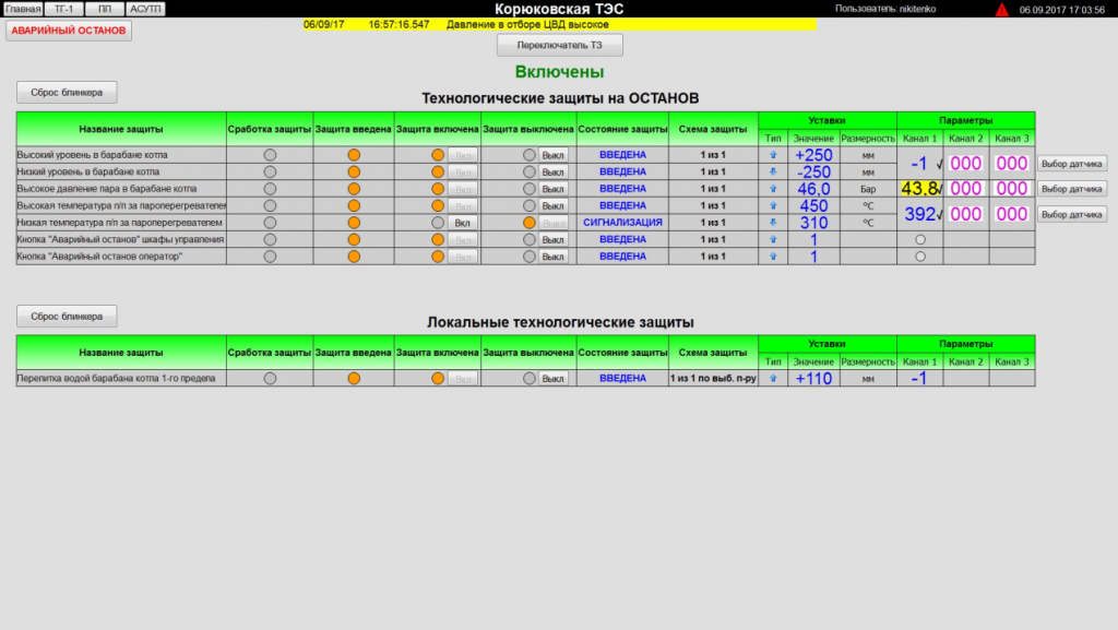
Safety functions detected abnormal conditions and acted to protect staff and equipment and contain the effects of a fault. The protection scheme used two-out-of-three voting, with signal-quality diagnostics. Analogue inputs from three sensors were distributed across three controller measurement modules so the protection function could remain available if one module failed.
Automatic sequences included a boiler trip response that stopped the moving floor, issued a furnace emergency-stop signal and opened the superheater purge valve; standby transfer between the two lift pumps and deaerator-level control; standby transfer between three feed pumps and feedwater-pressure control using variable-frequency drives; and automatic chip feed. In automatic mode, a furnace fuel-demand signal started or stopped the conveyors, screw feeder, hydraulic pump and moving floor in sequence, with timed loading and discharge delays.